The Clock Jobber's Handybook
By Paul N. Hasluck
Brought to you by:
Tick Tock Productions ™
The
CLOCK JOBBER'S HANDYBOOK.
PENDULUMS
THE CONTROLLERS.
CHAPTER IVI
DE WYCK'S, GERMAN AND HOUSE CLOCKS
The going part of a common regulator, or a house-clock of superior character, is shown by Fig. 14. Sir Edmund Beckett, in his " Clocks, Watches and Bells," gives an illustration from which the block herewith published is borrowed. The movement is that commonly found in the long cased hall- clocks—now only found as remnants of a past age, yet still very plentiful. These clocks appear to have an almost endless period of existence. They are made on far better principles than can be carried into effect in the confined space of mantel-clocks. Long, heavy pendulums give much greater regularity in action, and they are not so easily affected by irregularity in the motive-power.
Weights, again, are preferable to springs for the purpose of accuracy in time-keeping, inasmuch as the weight acts with a uniform pull, whereas a spring does not. Also, in transmitting the power of the spring to the wheel work, a more or less complex arrangement is necessary, which frequently absorbs much of the power that should be transmitted to the escapement. The mechanism is larger, and consequently less affected by particles of dust, &c., than in the modern smaller time-pieces. Keeping these peculiarities in view, the longevity of the old-fashioned hall-clock may be better understood.
Referring to Fig. 14, A a is one of the pallets on the arbor z, and F is the crutch and fork, which usually embraces the pendulum rod, but sometimes goes through it, as shown, especially when it is a wooden rod. The weight is hung not by a single line, but by a double one going round a pulley attached to the weight. This device prevents the line from untwisting, and a thinner one may be used; the fall of the weight is also only half as much as it would be with a single line. A larger barrel or a heavier weight frequently compensate for this. The barrel is fixed to its arbor; the back .end has an ordinary pivot, but the front is square, and prolonged to the dial at K. This is the wind-up square. G is the great wheel which rides loose on the arbor between the barrel and a collet shown just above G. The great wheel is connected with the barrel by a click and ratchet-wheel, the same as in De Wyck's clock, shown on page 48...
The great wheel, G, drives the centre pinion, c, which always turns completely once in one hour; its arbor goes through the dial and carries the minute hand. The dial wheels will be alluded to later on. The centre-wheel, C, drives the second pinion, d, which carries a wheel D, which drives the escapement pinion, and at the same time the wheel itself, E. Generally, in moderately good clocks, the pinions have all 8 teeth, or leaves; the wheels in that case have 96, 64, and 60 teeth in the centre, the second, and the escape respectively. This allows the escape-wheel to turn once a minute; and its arbor may carry a hand showing seconds.
In the diagram on page 63, the top pillar, Z, is shown prolonged to take a socket fixed on the dial-plate, and secured to the pillar by a transverse pin; the lower pillar, X, is similarly prolonged. The usual method is to have four short pillars riveted to the dial-plate, and made to pass through the front plate of the movement, where they are secured by transverse pins. The pillars used for connecting the frame are then cut off, just beyond the front plate.
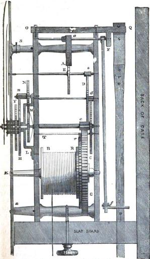
Fig. 14.—Movement of an Ordinary Long Case Clock.
On the left side the pendulum is shown marked P; it is- suspended from the traverse piece O Q by the spring S. This is called the suspension spring, and is simply a piece of mainspring. On the right the minute, hour, and seconds hands are shown in the order enumerated.
For the pillars of such a movement as this castings of various patterns and sizes are easily obtained. These are turned up in the lathe in the ordinary way, and made true and of equal length between the shoulders. To rivet these into the bottom plate, place all the pillars in their respective holes, and put on the top plate and secure the whole firmly together. Then rest the free ends, in which the pin-hole will be, one by one upon a hard wood block, and well rivet each pillar firmly in position. By this method the two plates forming the frame are put together perfectly square, and the plates are everywhere equidistant. The pin-holes are then drilled in the free ends.
The plates should be made of well-hammered brass of good quality, filed and finished quite smooth, straight and flat. They may be purchased ready prepared from the clock founder's. It is a difficult and tedious job to make them true to anyone not accustomed to such work. After filing up the clock plates, get a piece of fine pumice-stone, with which polish out the file marks, using the stone in a roundabout direction. After which, take a piece of water of Ayr stone, and rubbing from corner to corner of plate, take out all the pumice-stone marks, and finish up with fine pounded rottenstone and oil on a woollen buff often made of a lot of old stockings firmly tied together, with which polish right up and down the plate until a sufficient gloss is got. In the whole operation, cleanliness is necessary, observing that no particles of filings are allowed to come on the plate or on the polishing buff; and care must be taken not to run over the edges, so as to round them. The plates are finally finished, either with rottenstone, or by rubbing them with a flat piece of fine-grained charcoal well moistened with vinegar. When smooth and true they should be pinned together with two small pins near two opposite edges of the plates, and the positions of the various wheels set out in plan, also the holes for the pillars. The holes are then drilled through both plates while pinned together, taking care to keep the drill straight.
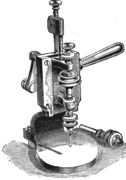
In order to ensure these holes being drilled through the plates quite upright, a special tool, as shown at Fig. 15, is often used. The tool illustrated has a vertical spindle, fitted with adjustable self-centering chucks to take drills of any sizes. The spindle is driven by a foot-wheel. The handle shown affords a most convenient means of feeding the drill, and there is an adjustable stop to gauge the depth in drilling. This tool is made entirely of iron and steel.
The dials of clocks of this type are usually made of polished brass plate; the figures are engraved, and filled with black sealing-wax, the plate being silvered according to the following directions.
Take a tablespoonful of the best cream of tartar, and ad about as much crystals of nitrate of silver as will lie on a shilling, dissolve in a very small quantity of water, and make it all into a thick paste; only just wet the cream of tartar. No metal of any kind must be brought in contact with it during the mixing. The beautiful effect on the clock-dial greatly depends on the regular emery-clothing of the brass plate. There should be no scratches seen before the plate is silvered; the grain or the marks of the emery cloth should be very regular and all one way; the emery cloth should not be too fine; the paste of cream of tartar and nitrate of silver to be rubbed on with clean fingers.
Common clocks have dials of sheet-iron painted white, and with the figures afterwards painted black. The common Dutch clocks have wooden dials; and so have some American clocks. French timepieces have enameled dials, but the commonest kind are simply cardboard.
Learn clock repair with these DVD courses! Course manuals are included.
Watch, study and learn antique clock repair through DVD course instruction using actual live repairs!!
Clock Repair 1 & 2 Advanced Clock Repair PRO advanced clock repair
Clockmaker Watchmaker Lathe Basics Clockmaker Watchmaker Lathe Projects Clock Case Repair & Restoration Wooden Works Movement Repair
© Copyright 2001-2009 by Tick Tock Productions © Copyright 2001-2009 by John Tope All rights reserved.
Back to clock information page.
Hasluck, Paul N. The Clock Jobber’s Handybook. London: Crosby Lockwood and Son, 1889.
This and the following pages are excerpts from the book.