The Clock Jobber's Handybook
By Paul N. Hasluck
Brought to you by:
Tick Tock Productions ™
The
CLOCK JOBBER'S HANDYBOOK.
PENDULUMS
THE CONTROLLERS.
CHAPTER V
EXAMINING AND CLEANING A 8-DAY CLOCK
In repairing an escapement it is well to spare no pains to make it as perfect as circumstances will admit, so as to obtain the best possible results. To do this, reduce the friction by making the acting faces of the pallets very smooth and of good shape; avoid all excessive drop and consequent loss of power, and render it as free as possible from liability to the variation of the motive force. To examine the escapement, place the third wheel and escape wheel in the plates, and pin together with the examining pins. See that the pallets and crutch are tight on their arbor, and observe whether the pallets are worn by the action of the escape wheel teeth. Now put in the pallets and screw on the cock, and see whether the holes of the pallet-arbor pivots are of proper size, as it is very important that these holes should be only large enough for the pivots to be just free. If found to be too large, remedy at once by putting new ones ; return the pallets to their place, and proceed to test the action of the escape-wheel upon the pallets by pressing forward the third wheel with one hand, and confining the action of the pallets by holding the crutch with the other, and then slowly moving it from side to side a sufficient distance to let each successive tooth " escape " the pallets.
The escapement when correct should fulfill these conditions : The drop on to each pallet should be equal, and only sufficient to give safe clearance to the tooth at the back of the pallet from which it has dropped; there should be as little recoil as can be obtained from the shape of the escape wheel; the pallets should not scrape the back of the escape wheel teeth. The faces of the pallets should be perfectly smooth, and of such shape as to require to be moved by the escape wheel before "escaping" a sufficient distance to ensure a "good action" or swing of the pendulum. As a general rule, it will be found sufficient if the end of the crutch moves nearly i in. from drop to drop of the wheel teeth. If the pallets are worn the faces must be filled up, at the same time taking advantage of the opportunity to make them a good shape.
The shape of these pallets is of great importance, and if the reader is not conversant with the subject, his safest course is to carefully study the information given. If this be attended to, and the drops adjusted as just described, the escapement will be as good as it was when the clock was new.
If the escapement be a dead-beat, and the pallets be much cut on the circular part, it will be difficult to retain the old pallets and make a good escapement. After the marks are taken out of the acting faces the pallets will be too thin, a certain amount of substance being necessary. In some instances, when not deeply worn, they may be repaired so as to last many years. The same directions for closing and altering the drops apply to this form of pallets as well as to recoil. The inclined planes, or impulse faces, have to be filed so that the teeth of the wheel will strike just beyond the edge of the obtuse angle.
Though it is proper to leave as little " drop " as possible, remember to give sufficient to ensure clearance after a little wear, and under disadvantageous circumstances, or else after going a few weeks, the pallets will catch and the clock will stop. When the edge of the inside pallet catches upon a tooth, the pallets are too close to the wheel; when the edge of the outside pallet catches, there is insufficient distance between the pallets. Some escape wheels are cut irregularly, and it is impossible to get a good escapement.
When the escapement is corrected, attend to the opening in the crutch; it should be sufficiently large for the pendulum rod to move freely, without side-shake; if at all rough inside, it must be made smooth and burnished, and then closed to the proper size.
The suspension of the pendulum, the pendulum spring, and the action of the crutch, or back fork, on the pendulum, are all of the most vital importance. The spring should be perfectly straight, and should fit into the slit of the cock without shake, and the slit should be perfectly straight, and at right angles to the dial of the clock.
The back fork should fit easily and without shake, and the acting part stand at right angles to the frames. The pendulum bob should swing exactly in a plane with the frames and the dial. After a movement has been put in its case, before putting on the head, it is well to get up high enough and look down to see that all these parts work as has been described.
See that the pendulum is sound everywhere; that the spring is not cracked or crippled; that the regulating nut and screw at the bottom act properly, and the bob slides easily on the rod. See also that the suspension is without shake; it should rest well on the stud, and fit sufficiently tight so that when the pendulum is swinging the suspension will not move at the top above the slit. This concludes the examination of the time-keeping parts of the clock, and the process should always be carefully gone through if good results are desired.
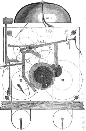
The "going" part of the clock having been repaired, it will be necessary to take a look at the striking works; and this part may be found to be considerably out of order. The illustration, Fig. 28 'represents the front of an ordinary English striking clock. It will be well to name the parts that are lettered. The escape-wheel is marked B. The hook or catch of the rack is C. The gathering pallet is G. The hour-wheel is H. The rack is marked B K R V. The hammer-spring is S. The hammer-tail is T. The motion wheels are M N H. The warning-wheel is next the fly; it has the pin, P, which stops the train after the clock has given warning, till the warning detent, L, is let fall by the pin N just at the hour, and allows the warning-wheel, P, to revolve. The lever marked si. and st., which mean silent and strike, is shown in position to allow the clock to strike, but if the outer end were raised the inner end would come against the pin in the rack arm, and so prevent the rack falling, and thus the clock would not strike. This lever is usually in a position to be moved at the will of the owner. The string at F
 Fig. 28.—Mechanism
of an Ordinary Striking Clock.
allows the clock to repeat its striking any number of times as often as the string is pulled downwards, and the striking train released by the lever F N L. The method of lifting the hammer is of importance, but the action of the hammer spring is but seldom right, especially if it be a spring bent over to a right angle near its end. If there are two springs, one to force the hammer down after the clock has raised it up, and another shorter one, fastened on to the pillar, to act as a counter-spring, and prevent the hammer from jarring on the bell, there will seldom be any difficulty. The only operations necessary are to file out worn parts, polish the acting parts, and set the springs a little stronger. If it be a spring of the first-mentioned construction, some further directions will be necessary, because the action of the one spring answers the purpose of the two in the last-named method. To arrange it so that the hammer will be lifted with the greatest Vease, and then strike on the bell with the greatest force, and without jarring, requires some experience. That part of the hammer stem which the spring acts on should never be filed beyond the centre of the arbor, as is sometimes done, because^in such a case the hammer spring has a sliding motion when it is in action, and some of the force of the spring is thereby lost. The point of the spring should also be made to work as near the centre of the arbor as it is possible to get it, and the flat end of the spring should be at a right angle with the edge of the frame. That part of the hammer stem that strikes against the flat end of the spring should be formed with a peculiar curve that will stop the hammer in a particular position, and prevent it jarring on the bell. This curve can only be determined by experience; but an arc of a circle six inches in diameter will be nearly right.
The action of the pin-wheel on the hammer tail is also of importance. The acting face of the hammer tail should be in a line with the centre of the pin-wheel, or a very little above, but never below it, for then it becomes more difficult for the pin-wheel to lift the hammer. The hammer tail should be of such a length as to drop from the pins of the pin- wheel and when at rest should be about the distance of two teeth of the wheel from the next pin. This allows the wheel- work to gain a little momentum before lifting the hammer, which is desirable. After setting the hammer spring to a greater force, it is always well, when the clock is striking, to stop the fly. If this remains stopped it indicates that the hammer spring is stronger than the power of the clock can bear, and it ought to be weakened, because the striking part will be sure to stop whenever the clock gets dirty.
_____________________________________________________________________________
Learn clock repair with these DVD courses! Course manuals are included.
Watch, study and learn antique clock repair through DVD course instruction using actual live repairs!!
Clock Repair 1 & 2 Advanced Clock Repair PRO advanced clock repair
Clockmaker Watchmaker Lathe Basics Clockmaker Watchmaker Lathe Projects Clock Case Repair & Restoration Wooden Works Movement Repair
© Copyright 2001-2009 by Tick Tock Productions © Copyright 2001-2009 by John Tope All rights reserved.
Back to clock information page.
Hasluck, Paul N. The Clock Jobber’s Handybook. London: Crosby Lockwood and Son, 1889.
This and the following pages are excerpts from the book.
