The Clock Jobber's Handybook
By Paul N. Hasluck
Brought to you by:
Tick Tock Productions ™
The
CLOCK JOBBER'S HANDYBOOK.
PENDULUMS
THE CONTROLLERS.
CHAPTER III
ESCAPEMENTS COMMONLY USED.
A piece of thin sheet metal is the best material to draw such a diagram upon; sheet zinc is convenient First drill a hole to represent the centre of the escape-wheel, and enlarge this to allow the axis of the escape-wheel to go through, and fit when the wheel lies in contact with the plate. Draw the various lines, by means of a scriber, so as to get the position of a pallet-centre, and then gauge the position of the actual pivot holes in the clock. Of course the hole must be drilled in the metal plate to correspond with the pivot hole in the clock. The hole is enlarged to fit the pallet axis, and the escape-wheel and pallets may be tried on the plate. Having due regard to any peculiarities of the especial escapement being examined, proceed to draw the various lines as indicated in the accompanying diagram, and any error in the form of the pallets will be shown by comparison.
The diagram, Fig. 9, is lettered in precisely the same manner, the proportions being, however, different. The diagram of the escape-wheel is drawn, and the radial lines D C are drawn through the points of two teeth, as shown. The lines E and N are drawn and their intersection at B gives centre of the pallets. The faces of the pallets are determined in much the same manner as previously described; the point 5 being five- sevenths of a semi- diameter from the point of the tooth. These illustrations are merely intended to show the extended application of the principles that have been explained.
The accompanying drawing, Fig. 9, will show the method of designing a pair of pallets to suit a particular escape-wheel. In the first place determine the distance apart of the centre of the wheel A, and the centre of the pallets B. If you are only replacing worn-out pallets, the holes in the plate will guide you. If you are making a new escapement entirely, the following method is useful: Draw radial lines from the centre of the escape-wheel A, through the points of the teeth embraced by the pallets. These lines are marked A C and A D in the drawing. At the point where the circumference of the wheel bisects these lines, erect perpendiculars shown by E B and F B; where they bisect B is the centre of the pallets. From this centre draw a circle through the points of the teeth embraced by the pallets. This circle is shown dotted in the illustration. A continuation of the line E B to H cuts this circle in half. Divide the half into seven equal parts marked 1234567, and from the point 5 draw a line through the point of the tooth. (See diagram). This gives the impulse face of the pallet a. A line drawn through the points of the two teeth of the escape-wheel, shown by K L, gives the face of the pallet b. The circle drawn inside of the one through the teeth is precisely midway between the points of the teeth. This marks the length of the pallet b. The amount of the face necessarily in contact with the escape-wheel between each escape is contained within the angle N B F, and amounts usually to about five degrees. A like amount is set off on the opposite side, M B E. This explanation will make the diagram clear.
 Figure
9.
Figure
9.
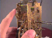
The American clock pallets shown at Fig. 10, are shaped by this method, though, perhaps at first sight, they hardly look so.

Fig. 10.—Pallets of American Clock made of Bent Steel.
Dead-beat clocks, having a seconds hand, and watches also, remain perfectly dead during the greater portion of time. The seconds hand jumps from one division to the next, and remains. With recoil escapements, the seconds hand will be observed to jump from one division to the next, but instead of remaining dead it goes backwards till the pendulum, or balance, has completed its supplementary vibration, then the hand goes forward gradually till the tooth escapes, then it jumps, and then the retrograde motion is repeated.
When the same cause produces precisely opposite effects on the two forms of escapement, the means of adjustment are obvious. It is necessary to modify the two forms, and this is now done successfully. Pallets should be so formed that they have but very little recoil, and then a variation in the motive force or in the arc of vibration of the pendulum will produce hardly any appreciable variation in the time-keeping.
Reid says that clockmakers in general have an idea that in an escapement the pallets ought to take in seven, nine, or eleven teeth, thinking that an even number could not answer. This is by no means essential. The distance from the centre of the pallets to the centre of the escape-wheel also is not determined by any rule. The nearer the centres the less will be the number of teeth that are required to be taken in by the pallets. When the arms of the pallets are long, the influence of the motive power on the pendulum will be greater than when they are short. The depth that the pallets engage in the wheel teeth will determine the angular motion of the pendulum necessary for the teeth to escape.
Learn clock repair with these DVD courses! Course manuals are included.
Watch, study and learn antique clock repair through DVD course instruction using actual live repairs!!
Clock Repair 1 & 2 Advanced Clock Repair PRO advanced clock repair
Clockmaker Watchmaker Lathe Basics Clockmaker Watchmaker Lathe Projects Clock Case Repair & Restoration Wooden Works Movement Repair
© Copyright 2001-2009 by Tick Tock Productions © Copyright 2001-2009 by John Tope All rights reserved.
Back to clock information page.
Hasluck, Paul N. The Clock Jobber’s Handybook. London: Crosby Lockwood and Son, 1889.
This and the following pages are excerpts from the book.