The Clock Jobber's Handybook
By Paul N. Hasluck
Brought to you by:
Tick Tock Productions ™
The
CLOCK JOBBER'S HANDYBOOK.
PENDULUMS
THE CONTROLLERS.
CHAPTER III
ESCAPEMENTS COMMONLY USED.
The
instructions for drawing a dead-beat escapement, I will quote from The
Watch And Clockmaker's Handybook. "
Draw a circle representing the escape-wheel, assuming it to have thirty
teeth, and the pallets to embrace eight of them, set off on each side of a
centre line the points as described with the recoil escapement. The
position for the centre of the pallets will be the point where tangents
drawn from the points of the teeth intersect. The width of each pallet is
equal to half the distance between one tooth and the next, less the amount
of the drop, this need be very little. The escaping arc is 2°, being 1°
30' for impulse, and 30' for repose. The width of the pallets may be got
by drawing radial lines barely 3° on each side of the points of the
teeth, then from the intersection of those radial lines with the
circumference of the wheel, draw arcs from the centre of the pallets, and
these arcs will be the faces of the pallets. From the centre of the
pallets draw lines through the points where the faces of the pallets
intersect the circumference. (These lines will be the same as those drawn
to find the centre of the pallets.) Mark off 1° 30', above this line on
the right, and the same amount below it on the left, where those lines
intersect the faces of the pallets these terminate.
A line from the intersection of the right to the outer face of the
pallet, where it intersects the circumference, will give the impulse plane
of that pallet. The other is got by the same method, remembering to make
the plane 1° 30' long. The escape-wheel should be very light, made of
hard brass well hammered; it is usually about one inch and a half in
.diameter. The pallets are frequently jewelled. A heavy pendulum is
necessary to unlock the escapement from the pressure of the wheel teeth on
the locking faces of the pallets. This is more frequently the case when
heavy weights are used, and these are necessary when the trains are not
perfectly accurate."
Detached
escapements are seldom used for household clocks. The gravity escapement,
invented by Mr. Denison, afterwards Sir Edmund Beckett, now Lord
Grimthorpe, and used for the great clock in
the Houses of Parliament, Westminster, is perhaps the most useful form of
detached .escapement. On each side of the pendulum hangs one of the
pallets, which are lifted by the pendulum during its swing, .and fall
again with it. But after each pallet has fallen as far as its own beat-pin
allows it to go, and before the pendulum returns to take it up again, it
is lifted a short distance by the action of the train, and, therefore, the
pendulum has not so far to lift it as it subsequently falls, and it is the
difference between these two amounts of work that goes to keep the
pendulum swinging. It is the weight of the pallets acting upon the
pendulum through this short distance that keeps up the motion; hence its
name—gravity escapement. The great advantage of this escapement over all
others* is the fact that the pendulum receives its impulse at a time when
the clock train is perfectly at rest.
The
drawing herewith (taken by permission from Sir E. Beckett's
"Rudimentary Treatise on Clocks, Watches and
Bells ") shows the escape-wheel and pallets of a four-legged gravity
escapement; all details of the various bearings are left out, as being
only likely to confuse. The peculiarity of a gravity escapement is that
the impulse is applied to the pendulum by a piece which is entirely
independent of the train, and acts solely from its own weight or gravity;
thus all imperfections of the train causing a variation in the power which
reaches the escape-wheel have no effect whatever on the vibrations of the
pendulum. The escape- wheel in the drawing has four long arms serving as
teeth, the front edge of these being in a straight line from the centre
(see Fig. u); at the centre of the wheel eight pins are fixed, projecting
but a short distance, about an eighth of an inch is enough, four alternate
ones on each side. These pins are made of steel, and must be well fitted
to the wheel, so that they will not become loose in use. On the arbor of
the escapement a large light fan must be fitted to revolve pretty freely;
this is to reduce the force of impact of the wheel teeth on the stop
pieces; the fly is shown and named in sketch. The pallets C T S are made
from sheet steel cut out to the shape shown; or they may be of any shape
whatever, so long as there are plans for fixing the stops S S in the
position shown, and the arms projecting towards the centre of the wheel
are available. It will be seen that the left-hand pallet is in front of
the wheel, and the other, the right-hand one, is behind the wheel.
The
axles at the pallets are at C, where two short arbors are fixed as shown.
At K K1 are shown two pins forming, banking
pins against which the pallets rest. Without these pins their natural
tendency would be to hang with the ends T T1
overlapping, owing to the weight of the arms at S S. The pins K K,
however, catch the pallets when they hang with the pins projecting from T
T, just touching the pendulum
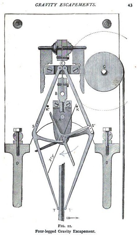
rod
when this is hanging at rest, which is the position in which the
escapement is now drawn. It will be seen that the tooth of the
escape-wheel is resting on the stop of the right pallet, and the left
pallet hangs with the point of the arm towards the centre wheel just clear
of the pin in the centre. This pallet is now quite detached from
everything, and may be lifted out without producing any effect, the pin K1
always preventing the pin in T bearing with any appreciable weight on the
pendulum rod.
The
motion of the escapement is thus imparted. By moving the pendulum towards
the right the right-hand pallet is lifted, and the escape-wheel tooth
resting on S1 is liberated, allowing the
wheel to revolve partially. The pin in the centre now catches the arm in
the left pallet, and lifts it till the wheel is stopped by a tooth
catching the stop on the left pallet; the weight of the right pallet
pressing the pendulum meanwhile drives it towards equilibrium and gives it
sufficient impulse to reach the left pallet, and lift it enough to allow
the tooth to escape, and the wheel in revolving, before it is stopped by
the stop S, lifts the right pallet by means of the pin in the centre
acting on the arm. Meanwhile the entire weight of the left pallet is
forcing the pendulum towards the right till caught by the stop-pin K, the
pendulum swinging by its own momentum far enough to lift the right pallet,
and so Ihe motion is kept up till the power of the train is insufficient
to supply force enough to the escape-wheel to raise the pallets
alternately.
There are many other forms of escapement, but most of them are seen but rarely; it is therefore unnecessary to allude to them. A form of escapement frequently seen in French time-pieces that have the escape-wheel exposed in front of the dial is the " Brocot," named from the inventor. The visible escapement is generally provided with semicircular ruby pallets. Those pallets are fixed into a brass anchor. The impulse is given by the action of the teeth of the wheel on the rounding face of the pallets. Great care is necessary in oiling these escapements, because it generally happens that oil applied to the pallets runs towards the anchor and there adheres, so that it is practically useless. With good jewels the want of oil is not productive of serious inconvenience, but steel pallets, sometimes found in the " Brocot " escapement, soon suffer.
The
pin-wheel escapement, invented by Lepaute about the middle of the last
century, is used for regulators and some turret clocks. The escape-wheel
is peculiar from having the teeth projecting parallel to the axis. The
pins are made of brass, and in some clocks they are round, but in that
case their diameter is very small. Half-round pins acting on their curved
faces are much stronger, and recently an improvement has been effected by
cutting a piece from the curved part of the semicircular pins. The pallets
for this escapement are made of steel, and are very near together, the
pins acting successively, so that the pallets embrace but one tooth. The
pin-wheel escapement has this advantage over the Graham, that it need not
be made so accurately, and that it will act when the pivot holes of both
wheel and pallet axes are worn, better than Graham's under similar
conditions.
Some
forms of " remontoir " were formerly used for turret clocks, and
others where the driving power is subject to considerable variation. The
"remontoir" consists of a contrivance, a spring or a weight,
which acts direct on the escapement, the contrivance being wound up by
means of the ordinary train at short intervals. Any irregularities in the
wheel work would thus have no influence on the escapement, and any power
might be added or withdrawn without in the least affecting the
time-keeping, providing always that there was sufficient power to act on
the " remontoir."
Learn clock repair with these DVD courses! Course manuals are included.
Watch, study and learn antique clock repair through DVD course instruction using actual live repairs!!
Clock Repair 1 & 2 Advanced Clock Repair PRO advanced clock repair
Clockmaker Watchmaker Lathe Basics Clockmaker Watchmaker Lathe Projects Clock Case Repair & Restoration Wooden Works Movement Repair
© Copyright 2001-2009 by Tick Tock Productions © Copyright 2001-2009 by John Tope All rights reserved.
Back to clock information page.
Hasluck, Paul N. The Clock Jobber’s Handybook. London: Crosby Lockwood and Son, 1889.
This and the following pages are excerpts from the book.