The Clock Jobber's Handybook
By Paul N. Hasluck
Brought to you by:
Tick Tock Productions ™
The
CLOCK JOBBER'S HANDYBOOK.
PENDULUMS
THE CONTROLLERS.
CHAPTER IVI
DE WYCK'S, GERMAN AND HOUSE CLOCKS
The illustrations given in this chapter show the construction of ordinary English clocks. Fig. 12 shows one of the first clocks of which we have any authentic description. It was made for Charles V. of France, in 1370. The vertical verge, shown in Fig. 12, was afterwards placed horizontally so that it might carry a weighted bob, or pendulum. To effect this alteration the escape-wheel had to be placed with it axis vertical, and it was driven by a crown wheel in the place of the wheel H. The illustration on page 63 shows the movement of an ordinary long-case hall-clock. These are frequently to be found in country houses, and are almost invariably heirlooms, in the conventional sense.
The clock made by Henry de Wyck, and briefly mentioned in a previous chapter, is shown by the illustration, Fig. 12. This is handed down to us as one of the most ancient balance clocks, and a description of its going parts will be interesting for comparison with that shown by Fig. 14, which is a superior kind of house clock and will be described later on.
Referring to Fig. 12, and describing it minutely, we shall get acknowledge of the various parts, their names and functions. Reid's "Treatise on Clock and Watch-making," published upwards of half a century ago, contains the illustration here copied, and also the description.
It has a weight suspended by a cord, which is wrapped round a cylinder or barrel keyed spring-tight on an axis or arbor a a, whose smaller parts b b, called the pivots, fit into holes made in the plates C C and D D, in which they turn. These plates in the ancient clocks were made of iron, and put together by the kneed pieces E E, which are formed from the ends of the plate C C. A screwed part at the extremity of the knees connects this plate by nuts to the plate D D. This assemblage of the plates and kneed parts is called "the frame."
In modern clocks the plates are invariably made of brass, and they are held together by means of pillars, also made of brass. The pillars are riveted into one plate, and have the other end shaped to form a shoulder, with a pivot-like projection. A pin, put diametrically through this projecting part, secures the second plate. A glance at Fig. 14 will show this. In Fig. 12 the action of the weight necessarily tends to turn the cylinder B, so that if it was not restrained, its descent would be by an accelerated motion, like that of any other body which falls freely. But the cylinder has at one end a toothed ratchet-wheel F, the teeth of which strike or butt on the end of the click c. The click is pressed by a spring d, which forces it to enter the ratchet-wheel. This mechanism, which is called the click and ratchet work, is the means by which the weight, when wound up, is prevented from running back. The action of the weight is in this way transmitted to the toothed-wheel G, which is thus forced to turn. The teeth of this wheel gear with the small wheel, which, technically speaking, is called the lantern-pinion e, and thus the axis/ is made to turn. This gearing, which, by the communication of motion from one wheel to another, or from a wheel to a. pinion, causes it to rotate, is technically called the pitchings or depths.
Movement of De Wyck's Clock
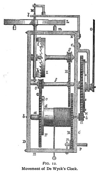
The wheel H is fixed on the arbor of the lantern-pinion e ; thus the motion communicated by the weight to the wheel G is transmitted to the pinion e, and consequently to the wheel H, causing it to turn on its axis f. The last-named wheel pitches into the lantern-pinion g, the axis of which carries the crown-wheel I; this is called the escapement-wheel, or, in trade language, the escape-wheel. We have traced how the motion of the descending weight is transmitted through a variety of pitchings to the levers or pallets h and i, which project from the vertical axis, thus moving on its pivots at the ends. It is on this last axis that the balance or regulator L is fixed. The balance is suspended by the cord M, and can move round its pivot in arcs or circles, going and returning alternately, making vibrations. The angle-piece, screwed to the frame at E, and marked /, forms a bearing for the top pivot of the verge.
The balance L is formed of two thin arms projecting from the verge; on these arms several concentric notches are made; a small weight m is appended to each arm. By placing the weights m nearer to or farther from the axis, the vibrations will be shortened or lengthened, and the clock made to go faster or slower. The action of the escape-wheel I on the pallets h i is called escaping.
The wheel G makes a revolution in one hour. The front pivot b of this wheel is prolonged beyond the plate C; it carries a pinion «, which pitches in, or leads, the wheel N, and causes it to make a turn in twelve hours. The axis of this wheel carries the index, or hand, O, which points out the hours on the dial.
It must be explained what determines the wheel G to make one revolution precisely in one hour; for this purpose, it must be known that the vibrations of the regulator or balance are slower as it is made heavier, or the diameter is increased. Suppose that the balance L makes vibrations exactly equal to one second of time, this may be regulated in the manner already mentioned, by moving the weights m. This being understood, it may be shown how, by properly proportioning the numbers of teeth in the wheels and pinions in the train, the wheel G may be made to make one revolution in exactly one hour. With 30 teeth in the escape-wheel I, the balance will make 60 vibrations for each turn of the wheel; the teeth acting once on the pallet h and once on /. According to the former calculation, the escape-wheel will make one turn in each minute, and the wheel G will have to make one turn to every sixty turns of the escape-wheel.
To determine the number of teeth in the wheels G and H, and hi their pinions, it must be understood that a wheel and pinion geared together turn in inverse ratio to the numbers of their teeth. Supposing the wheel G has sixty-four teeth, and the pinion e eight teeth, this pinion will turn eight times to every turn of the wheel. This is self-evident, for the wheel and the pinion move simultaneously tooth for tooth ; every turn of the pinion allows the wheel to turn a distance equal to the same number of teeth—that is, eight. Every turn of the wheel allows the pinion to turn through sixty-four teeth, or to make eight complete turns.
The wheel H having sixty teeth, and the pinion g eight teeth, the proportion is as 7^ is to i. Thus the pinion makes seven-and-a-half turns to each one of the wheel. The wheel H carries the pinion e, making eight turns to one of the wheel G; then the pinion g makes eight times seven-and- a-half turns, or sixty turns to each one turn of the wheel G. Having supposed that the wheel I, turning with the pinion g, makes one revolution in a minute, it is obvious that the wheel G makes a turn in one hour.
By the same reasoning, we see that the pinion u carried by the wheel G makes twelve turns during the time that the wheel N makes one. This wheel must have twelve times more teeth than the pinion. Ninety-six teeth in the wheel N, and eight teeth in the pinion u, will answer the purpose. Twelve pins project from the side of the wheel N; these pins are for the purpose of discharging the striking-gear.
Learn clock repair with these DVD courses! Course manuals are included.
Watch, study and learn antique clock repair through DVD course instruction using actual live repairs!!
Clock Repair 1 & 2 Advanced Clock Repair PRO advanced clock repair
Clockmaker Watchmaker Lathe Basics Clockmaker Watchmaker Lathe Projects Clock Case Repair & Restoration Wooden Works Movement Repair
© Copyright 2001-2009 by Tick Tock Productions © Copyright 2001-2009 by John Tope All rights reserved.
Back to clock information page.
Hasluck, Paul N. The Clock Jobber’s Handybook. London: Crosby Lockwood and Son, 1889.
This and the following pages are excerpts from the book.