The Clock Jobber's Handybook
By Paul N. Hasluck
Brought to you by:
Tick Tock Productions ™
The
CLOCK JOBBER'S HANDYBOOK.
PENDULUMS
THE CONTROLLERS.
CHAPTER IVI
DE WYCK'S, GERMAN AND HOUSE CLOCKS
When
the clock has been in action sufficiently
long, the cord by which the weight is suspended wholly runs off the
cylinder. Then the clock requires to be
" wound up." A key, having a square hole in its cannon to fit
the square arbor P, is used, and by this key the weight is wound up. The
wheel R and the ratchet-wheel F, together with the barrel, turn
independently of the wheel G. The ratchet and click motion have already
been explained. On ceasing to wind, the pressure of the weight against the
click forces the wheel G to turn with the cylinder, and so transmits the
power through the train to the escape-wheel. The small pinion n, on the
arbor P and \ gearing with R, is not used in modern clocks, as may be seen
on reference to Fig. 14.
Reid says that either Julien le Roy or Berthoud must have made a mistake in giving thirty teeth to the escape-wheel of De Wyck's clock. It is well known that the crown-wheel, or verge escapement, necessitates the use of a escape-wheel having an odd number of teeth. With the verge passing diametrically across the escape-wheel, an even number of teeth would not act on the pallets. Had the number been twenty-nine, all would have worked well, only the weights when on the balance would require to be adjusted so that they allowed the vibrations to equal fifty-eight per minute instead of sixty, the number required for a wheel of thirty teeth.
The clock made by Henry de Wyck, or de Vick, as he is sometimes called, has been considerably improved; but, as Sir Edmund Beckett says, it was very like our common clocks of the present time, except that it had only an hour hand, and a vibrating balance (but no balance-spring) instead of a pendulum. It seems strange that the apparently simpler contrivance of a pendulum should not have come till four centuries after clocks were first invented; yet this is the general tradition.
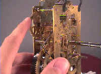
The illustration, Fig. 13, shows the interior of a clock of the cheapest description; it is called a Dutch clock, though more popularly known as the common kitchen clock. These time-keepers are made in the Schwarzwald (Germany), where labour is cheap, and the cost of production has been diminished to such an extent that some clocks made there are sold in London at the ridiculously low price of fifteen pence retail, and their prime cost of manufacture must amount to but a few pence.
The American productions have, in recent years, to a great extent superseded the so-called Dutch, but statistics show that twenty years ago there were in the Black Forest nearly 1,500 manufacturers, who employed 13,500 workpeople, and produced nearly two millions of clocks yearly. Various kinds of clocks are included in this aggregate. One of the cheapest is shown in the accompanying illustration, but "cuckoo" clocks and regulators are also made in the Schwarzwald.
One of the most noticeable peculiarities in these clocks is that they have lantern pinions. It is only for work of the highest class and most costly description that lantern pinions have hitherto been used in English clocks. That they are far superior in many ways, as compared with ordinary leaved pinions, has been practically demonstrated. Why makers of English clocks will not adopt lantern pinions is a question that appears very difficult to answer. It is not out of place here to discuss the merits of the two forms of pinion ; and the observant clock-jobber will not fail to notice how much better the gearing is with lantern pinions; and also it may be mentioned, that the wheel teeth need not be cut so accurately as when used to drive ordinary leaved pinions.
There are two kinds of solid pinions—one " drawn," and generally used, the other " cut," and not so frequently met with. All English clocks, with the exception of very fine regulators and turret clocks, have pinions made of pinion wire. This is sold at tool-shops in sticks of a foot or so in length, and is made by drawing steel through drawplates having holes corresponding with the sections of the pinions. Various sizes and numbers of leaves are kept in stock, and no difficulty need be found in getting whatever is wanted for ordinary clockwork.
A drawn pinion is prepared thus: first cut off a piece of pinion wire to the proper length; mark the place for the pinion, and strip off the pinion leaves from that portion which will not be required. File a notch both sides of the piece intended for the pinion, and then either break off the superfluous leafed part by screwing it tight in the vice, or file it down to the body, taking care not to bend this. It must now be pointed at both ends to run true in the turns, throw, or lathe, and turned smooth and parallel. The throw is a kind of small lathe, with dead centres, but instead of being worked by foot has a small fly-wheel turned by hand. It was formerly considered imperative that pinions should always be " turned in " between dead centres, it being thought almost impossible to keep them true between the live centres of an ordinary lathe, but now the running mandrel lathe is used for the very finest turning in watch work.
If the pinion is a cut one, it will be already centred and turned; the leaves will be cut to the proper shape, and this must be very carefully done with a circular cutter of a shape precisely suited to the particular wheel. The next step is to turn the seat for the wheel, if this is to be riveted direct on to the pinion, or else to make the brass collet, and solder it on in its position. The collet is best roughed out on an arbor (Fig. 49), but finished after being soldered on the pinion. Great care must be taken in either case to turn it absolutely true, and fit the wheel on very tightly; a wheel well fitted is half riveted, but a wheel badly fitted is never satisfactory. The pinion must now be polished, using first oilstone-dust and oil upon a piece of wood cut to shape, and then crocus and oil. The pinion arbor should now be polished, and the hollows cut in the pinions, if thought desirable. Lastly, the pivots are turned, and the wheel riveted on its place.
The other form of pinion to which we have referred is the lantern pinion, used throughout American clocks, and, as a proof of the cheapness of lantern pinions, they are also invariably used in the wooden "Dutch clocks," which are manufactured on the most economical principles. It appears to be a very old form of pinion, and in clockwork where the pinions are always driven, except in the motion work, it works with much less friction. Lantern pinions will run with wheels having less accurately cut teeth than are necessary for the leaved pinions.
Why English clockmakers do not use lantern pinions instead of the solid pinion wire is a mystery. True, the machinery to make lantern pinions would cost a few pounds, but if they were manufactured largely, and sold cheaply, there would be a large demand for them, if the working clockmakers would only see their superiority. If it is desired to make a set of lanterns to suit a particular movement, this can easily be done on the ordinary lathe, fitted with driving plate and drilling spindle. The diameters of the pinions will be proportionate to the diameters of the wheels with which they gear, in the same ratio as the trundles are to the teeth; but the form of the wheel teeth is usually somewhat different to the ordinary, though these suit almost as well.
In the American clock factories they have a special machine for making lantern pinions, as they have for every other part, and this, tended by one man, turns out some fifteen hundred pinions a day, which, for accuracy and price are scarcely to be surpassed. The six or eight equidistant holes for the trundles are bored in the brass collet on a machine something like a lathe, the back centre being fitted as a drilling spindle, and the headstock being fitted with dividing gear. On the front is a self-centring hollow chuck to grip the brass collet. This headstock can be set back from the line of centres by a micrometer screw, and thus the radius of the pinion is adjusted.
For drilling, a flat-ended drill is used, revolving at a high speed in the back centre part. This has a shoulder to prevent its going in too far. The collets are not bored through. The wire trundles bottom on the one side, and are held in the other by having the holes slightly burred over. The holes are thus bored one at a time, the drill being brought up by a lever, till the whole circle is finished. The round steel wire for the trundles is cut into lengths in large quantities, and is put into the holes by hand ; the outer end of the open hole is then burred over with a punch. This rough outline, shows how large quantities are made. A few lantern pinions wanted for a fine clock may have their collets drilled on a six-inch lathe with the drilling spindle as previously mentioned.
Let us now glance at the illustration, Fig. 13. It shows the common so-called Dutch clock that may be found hanging in many kitchens, and which is a most trustworthy time-keeper. Each side of the movement of clocks of this description is provided with a door, and when one door is unhooked from its hinges, the movement is disclosed, as shown in the illustration. By means of the lettering the various parts may be described. A A show the top and bottom of the whole movement, and into these the uprights B B, which form the bearings for the wheel axes, are mortised. One of the pieces B B, usually the front one, is easily removed, to take out the wheel-work, by being pressed outwards. C is a piece to which the ends of A A are fixed; D is the dial; and E the back, by which the clock is hung on a nail. This nail enters a hole in the upper part, not shown, the legs FF serving to keep the ,clock away from the wall sufficiently to leave a space for the pendulum, G, to .swing clear.
The wheel- work is shown towards the left. H is the axis of the great wheel,. which turns once-every hour. Fig. 13.
This axis also Movement of German Clock carries the pulley on which the weight-cord, R, is wound; also the minute- wheel, O, and the hour-wheel, S. The explanations given in the previous part of this chapter will enable the beginner to understand the working of these ,wheels O and S, which, together with P, form the motion work. The great wheel on H usually has 56 teeth, and it gears into the pinion, having 7 trundles, I. On the same axis, or arbor, is a wheel which drives the pinion J, and this carries the escape-wheel. The escape-wheel, of course, is entirely different from the others, its teeth being formed to drive the pallets on K. The axis of the pallets has a wire fixed in it, which protrudes at the back of the clock, and forms the crutch L, with a horizontal hook at the lower end, which embraces the pendulum rod, G.
 Fig. 13.
Learn clock repair with these DVD courses! Course manuals are included.
Watch, study and learn antique clock repair through DVD course instruction using actual live repairs!!
Clock Repair 1 & 2 Advanced Clock Repair PRO advanced clock repair
Clockmaker Watchmaker Lathe Basics Clockmaker Watchmaker Lathe Projects Clock Case Repair & Restoration Wooden Works Movement Repair
© Copyright 2001-2009 by Tick Tock Productions © Copyright 2001-2009 by John Tope All rights reserved.
Back to clock information page.
Hasluck, Paul N. The Clock Jobber’s Handybook. London: Crosby Lockwood and Son, 1889.
This and the following pages are excerpts from the book.